 [1]
[1]
A factory vehicle is fine and dandy for most folks, but for the automotive enthusiast, the itch to modify and customize begins almost the moment he or she drives the vehicle off the dealer lot. Even if the vehicle is purchased from a previous owner and already modified, the urge to customize and make it your own by re-molding it to suit your own needs, purposes, and personality is ever-present.
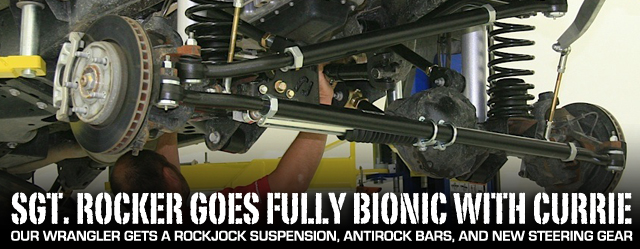
In the case of our 2013 Jeep Wrangler JKU Project Sgt. Rocker [2] the motivation to modify was more like the thirst of a man who had been walking through the desert for days. Once we began to drink, our thirst became unquenchable. A graphics makeover started it all, more was to come, and more is still planned, but the cornerstone of the build was to be a suspension kit that would elevate it to master rock crawler status. For that solid foundation, we chose the Currie Enterprises [3] RockJock CE-9807 JCE [4] Off Road Suspension System.
 [5]
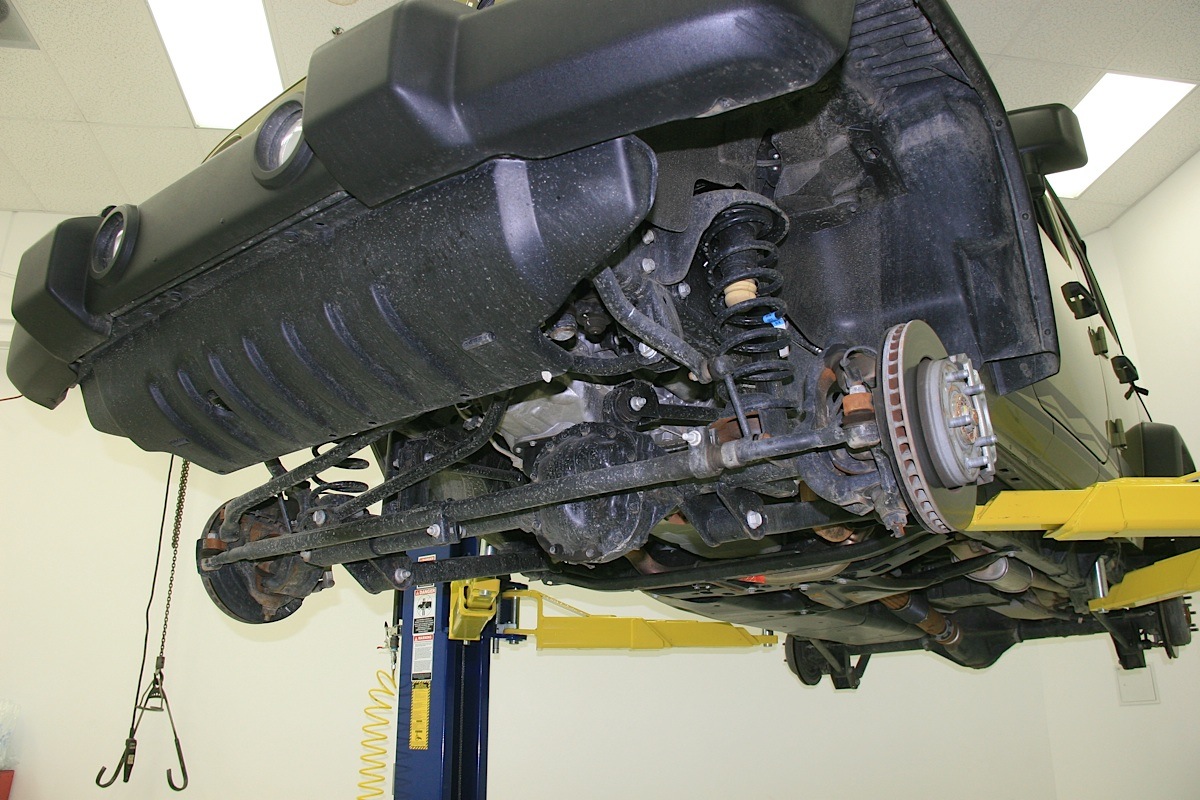
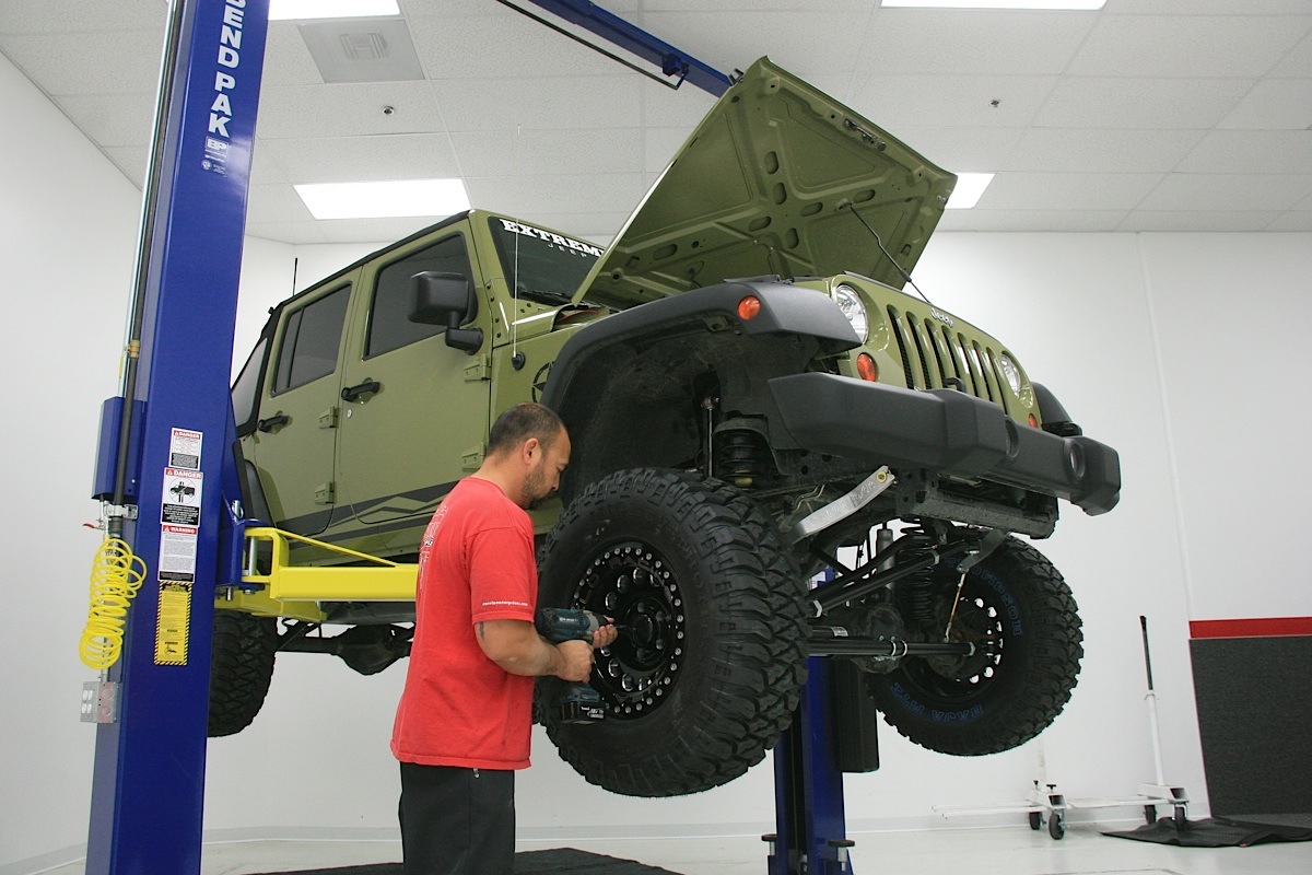
[5]We securely placed the Wrangler on a lift before taking off the wheels, tires and other stock suspension parts that needed to be removed prior to beginning the installation of the Currie RockJock suspension system, Antirock Sway Bars, and Currectlynk steering system.
It provides ample lift to accommodate up to a 37-inch tire, delivers approximately a four-inch lift, and up to 11 inches (38 percent increase over stock) of front and rear wheel travel. The system was designed around a 17×9-inch wheel with a 4-1/2-inch backspacing. Other wheel and tire combos can be used but may create interference issues.
Any load point where there’s articulation features a Johnny Joint. – Brian Shephard

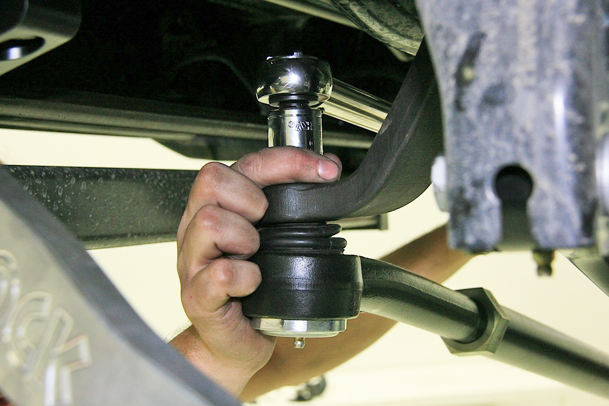
“Our [suspension] kit is complete. It has eight replacement control arms instead of just four like a lot of kits, and all eight arms have Johnny Joints at both ends. Any load point where there’s articulation features a Johnny Joint,” said Brian Shephard of Currie Enterprises.
 [7]
[7]One of the keys to the Currie RockJock suspension system are the beefy and well-articulating Johnny Joints at all load points.
What’s more, Currie Enterprises offers its Currectlynk heavy duty steering system [8] that offers a seriously beefy upgrade to the stock drag link and tire rod. The kit also provides a steering stabilizer bracket kit, and is exactly the sort of thing we were looking for to manage big meaty tires and wheels that were going to see severe off-road duty.
This is a full-featured and complex suspension system, and although it can be done by an experienced mechanic, it does require welding on some critical components. Before you begin this installation, you should read the complete instruction manual and understand it thoroughly. All the factory hardware is to be kept and reused unless otherwise specified in the instructions.
 [9]
[9]
Starting Line
Only then should you remove the tires and wheels. Once our Jeep was stripped of its rims and rubber, we removed the rear left (driver side) brake caliper, caliper bracket and rotor. Next, off came the bracket that secures the emergency brake cable wire bracket to the center of the Jeep’s floor above the fuel lines.
Then we removed the front clip that holds the ABS sensor wire on both sides on the rear upper control arm brackets. Using a jack, the rearend was lifted a couple of inches to take pressure off the system, so both rear shocks, the rear track bar, and the OE anti-sway bar links could be removed. The jack was then lowered slowly and the rear coil springs removed. Be careful, the coils can fall out of their upper perches during this procedure.
“Our adjustable track bars are substantially stronger than stock.” – Brian Shephard
The grease fittings of the Johnny Joints should be on the same side, point down on the upper arms, and point up on the lower arms. The adjustable ends attach to the rearend on the upper arm, and to the frame on the lower arm. Don’t fully torque the bolts yet.
 [10]
[10]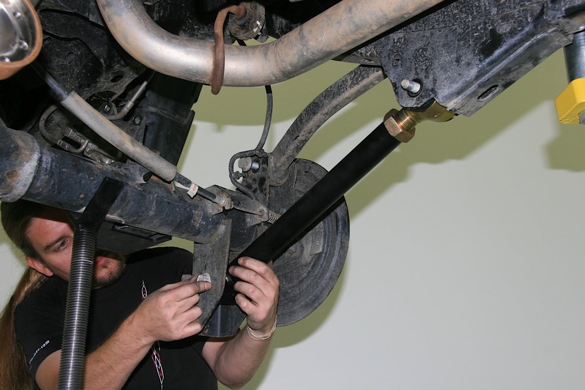 [11]
[11]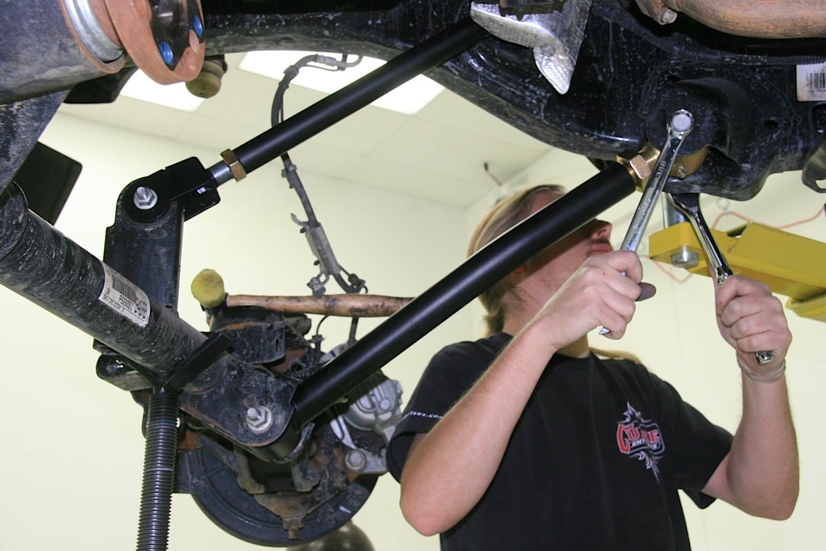 [12]
[12]
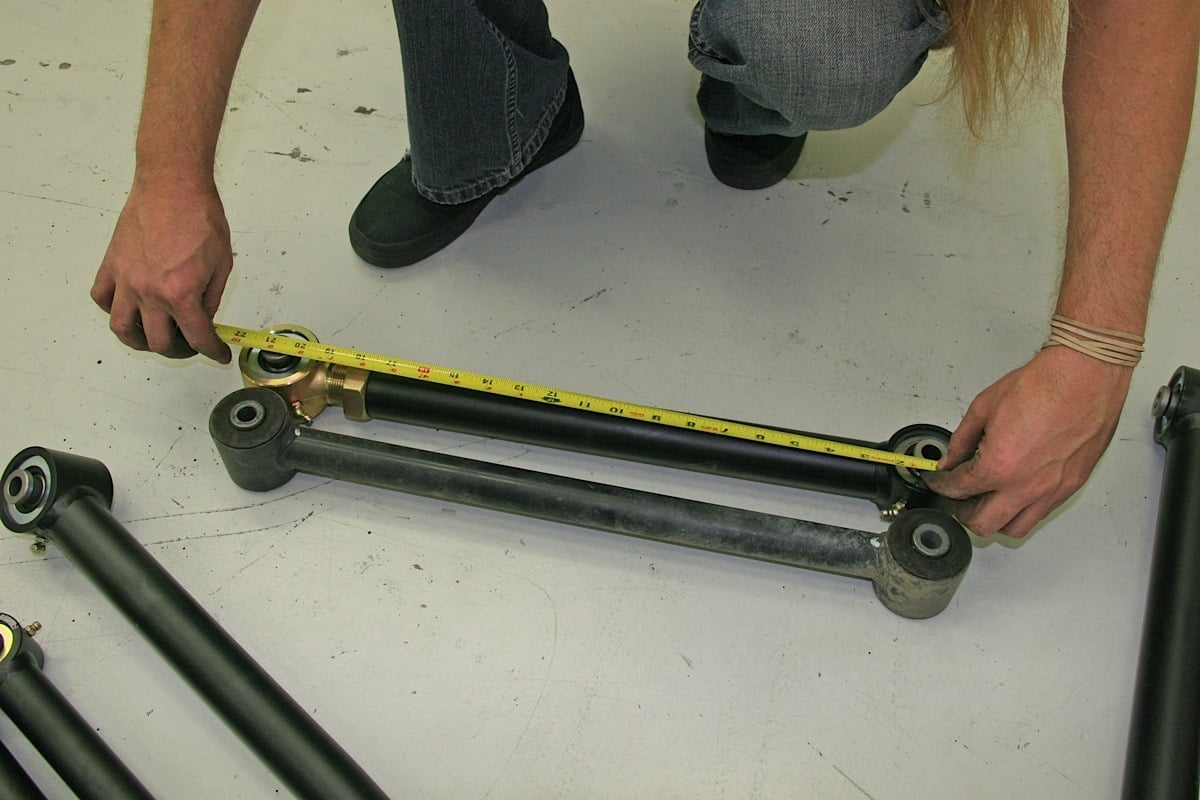
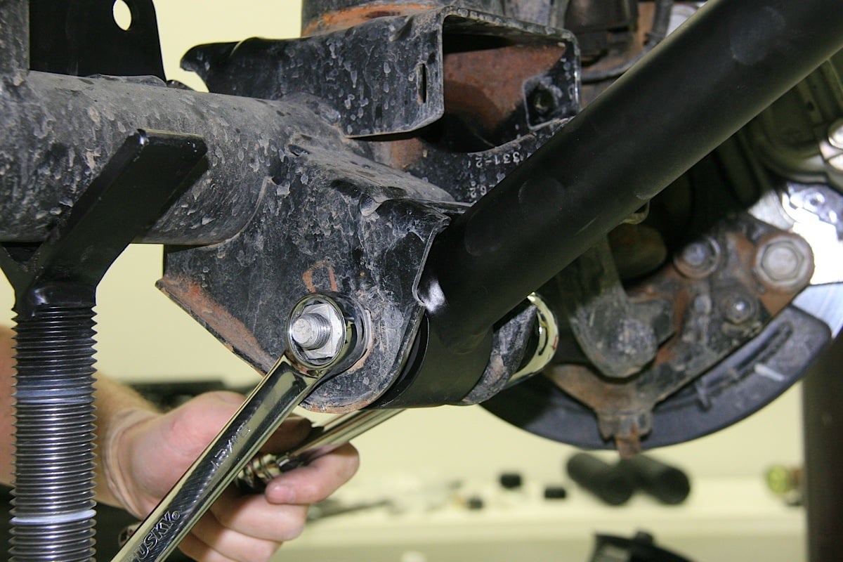
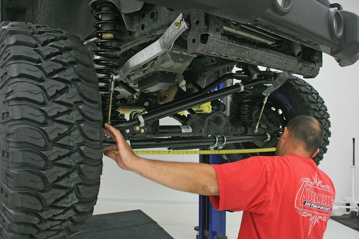
The new rear control arms were measured to match the length of the stock arms, replaced one at a time, and tightened up but not fully torqued yet.
Next we began the installation of the Currie rear track bar relocator. There is some welding required here, and we had already removed the factory track bar. Hold the Currie rear track bar relocator bracket in place to mark the area you need to clean paint off for later welding.
The track bar bracket was installed using the supplied 9/16-inch hardware and a 1.125 x 1.60-inch long spacer. We used a 7/16-inch bit next to drill a hole on the side of the factory track bar bracket, using the hole on the Currie bracket as a pilot.
 [13]
[13]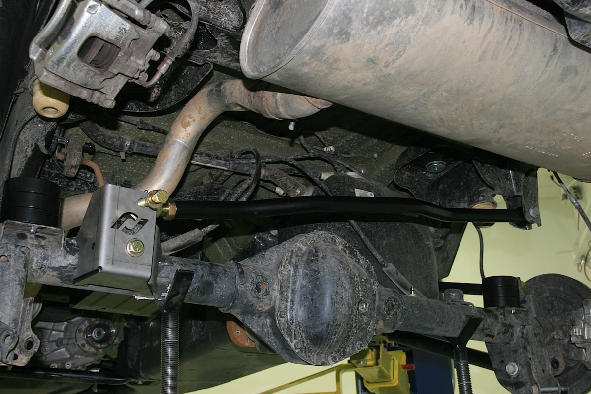 [14]
[14]
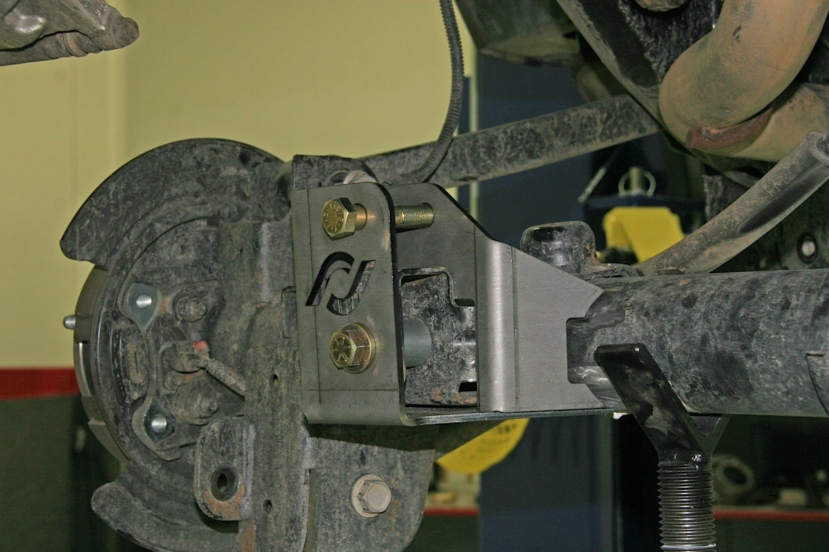
The new Currie rear track bar bracket was installed, then the new adjustable track bar was hooked up.
The bracket was then installed with the 7/16-inch hardware and tightened. The new Currie adjustable track bar was temporarily installed to help properly align it for welding. The beefy replacement track bars are a real plus. “Many kits don’t come with new track bars. Our adjustable track bars are substantially stronger than stock,” added Brian Shephard.
We stitch-welded the new bracket in place along its perimeter bit by bit, allowing the work to cool between welds so the axle tube would not warp. If you don’t own a welder or are not sure of your skills, tow your Jeep to to your local certified welder after installation. The track bar bracket needs to be bolted and welded. Lacking the proper weld job, the factory bracket will fail. After the weld cools, you can re-paint.
 [15]
[15]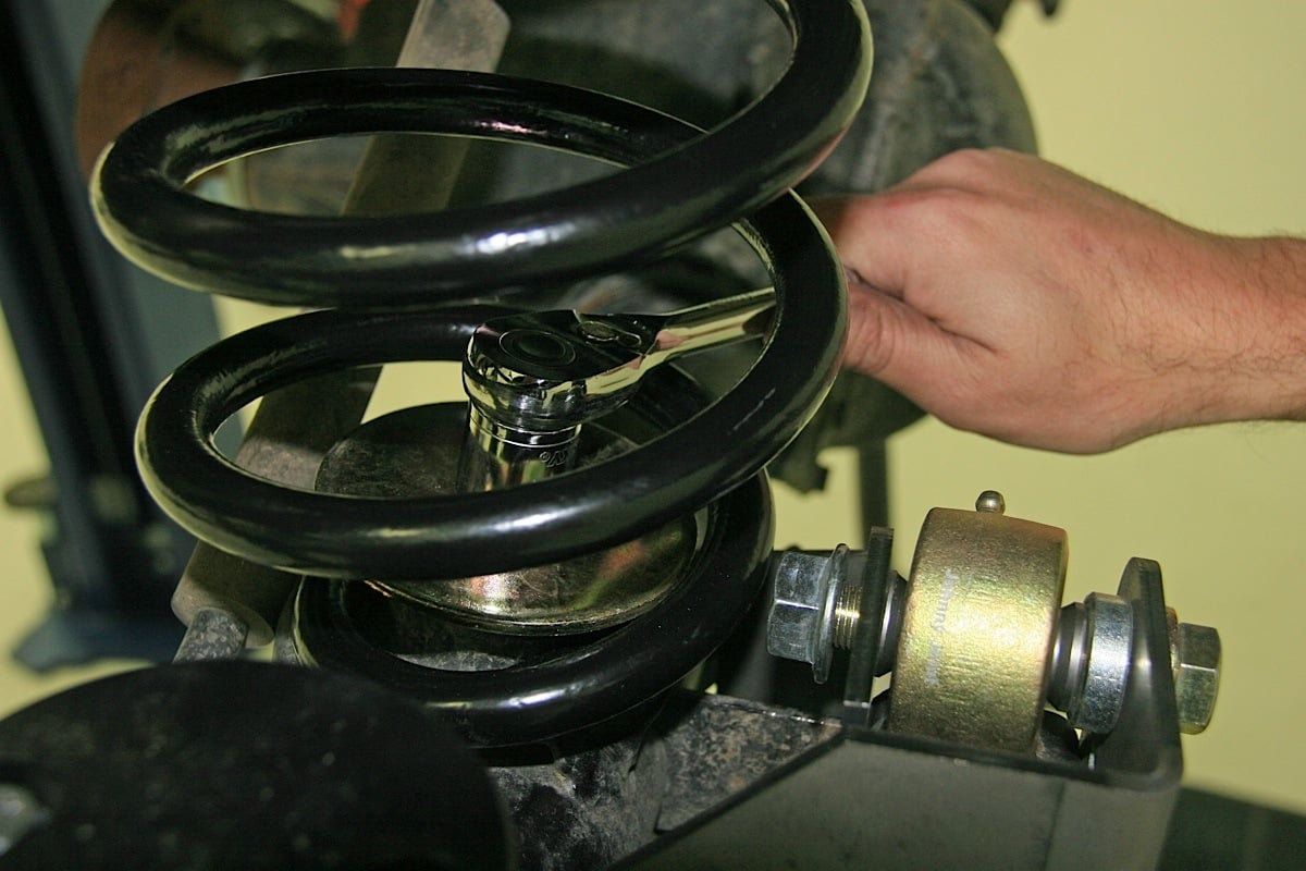 [16]
[16]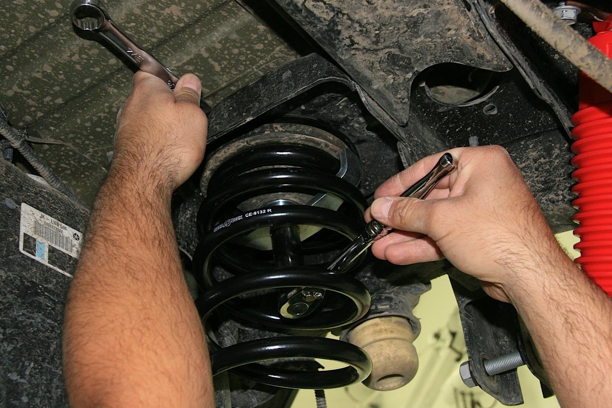 [17]
[17]
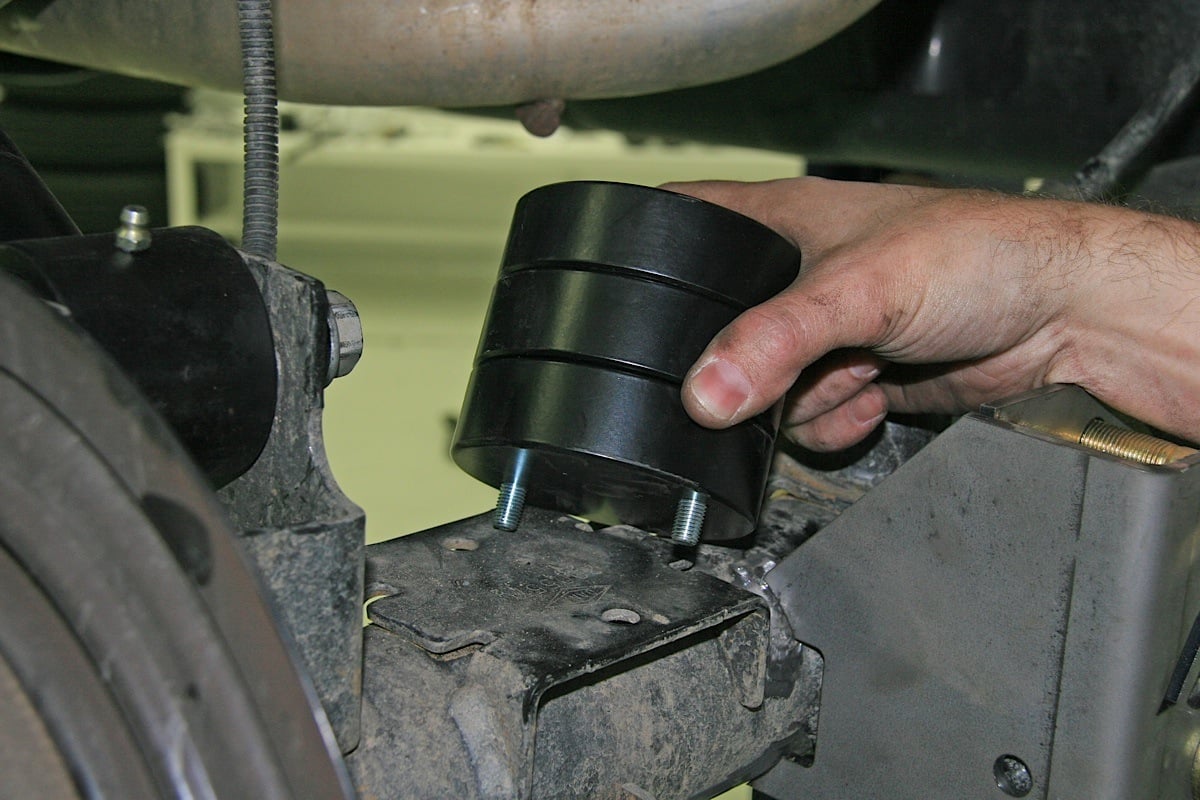
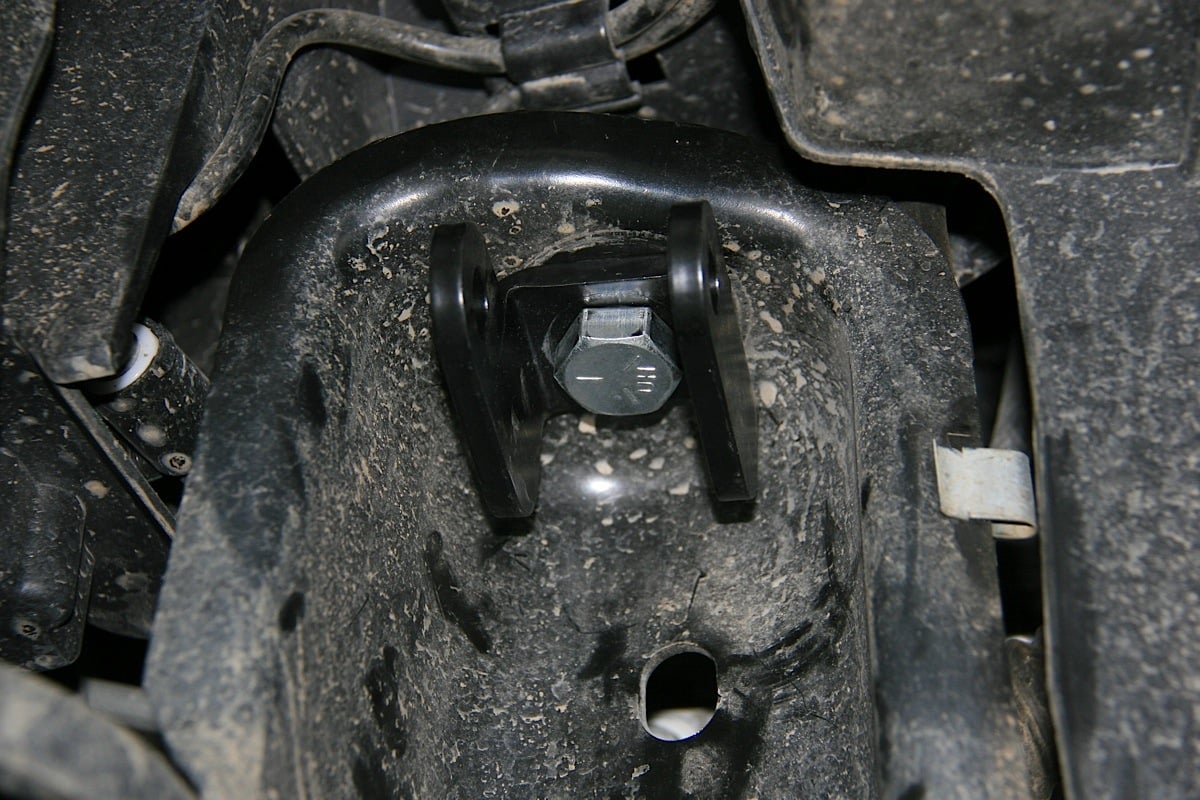
The new rear bump stops are located on the stock perches. The bottoms of the rear springs are fully fastened from within using retaining washers. The tops of the rear springs are also fastened to their mounts from within using c-clip retainers.
Next on the list were the rear bump stops. They were easily installed on top of the spring perch using the kit supplied hardware. It may be convenient at this time to install the Currie Antirock rear swaybar links. We then re-installed the left rear brake caliper and bracket.
Now it was time to install the new rear springs. The new track bar was removed for easier access during this operation, and because final adjustment of the new rear track is to be done later. We began with the spring retainer bungs on the top side of the frame, then the spring retainer spacers inside the top spring rubber isolators. The upper spring retainer clamps were secured using the 1/2-20 x 2 1⁄2-inch bolts and 1/2-inch washers. The clamps must be at a 90-degree angle to the end of the coil.
We had to hold the 1/2-20 nyloc nuts and the other two 1⁄2-inch washers, reach above the frame, and install them onto the 1⁄2-inch bolts. While holding a wrench on the top and a ratchet and socket on the bottom inside the spring, we then tightened this hardware to hold the top of the rear springs in place.
To secure the bottoms of the springs, the spring retainers (3-1⁄2-inch OD x 1/2-inch ID washers) were placed onto the rearend housing with the 1/2-13 x 1-inch thread forming bolts and the bottom spring retainer nutplates. Use some Red Loc-tite on the threads, but don’t over tighten the bolts, just tighten enough to secure the spring retainers to the housing.
 [18]
[18]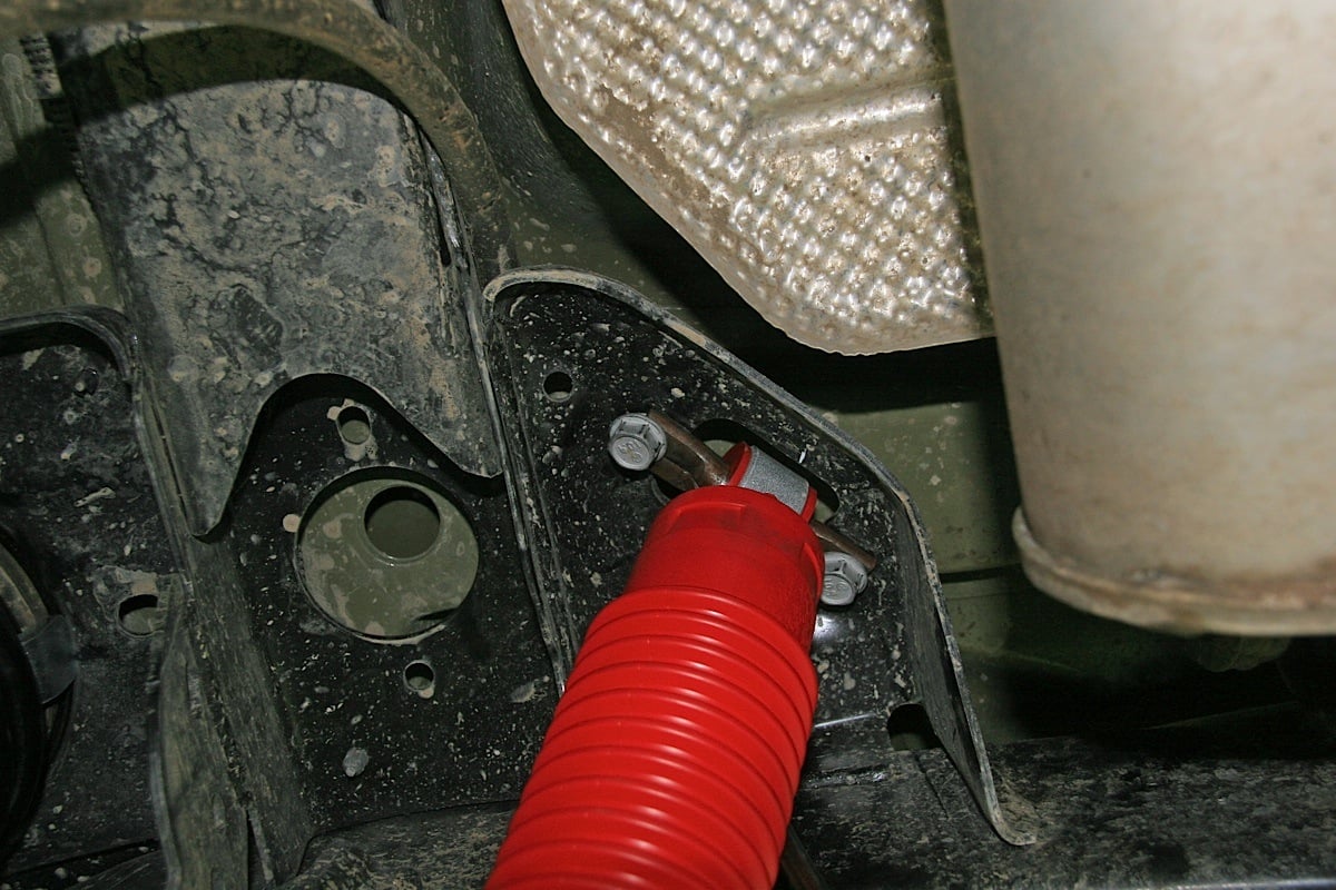 [19]
[19]
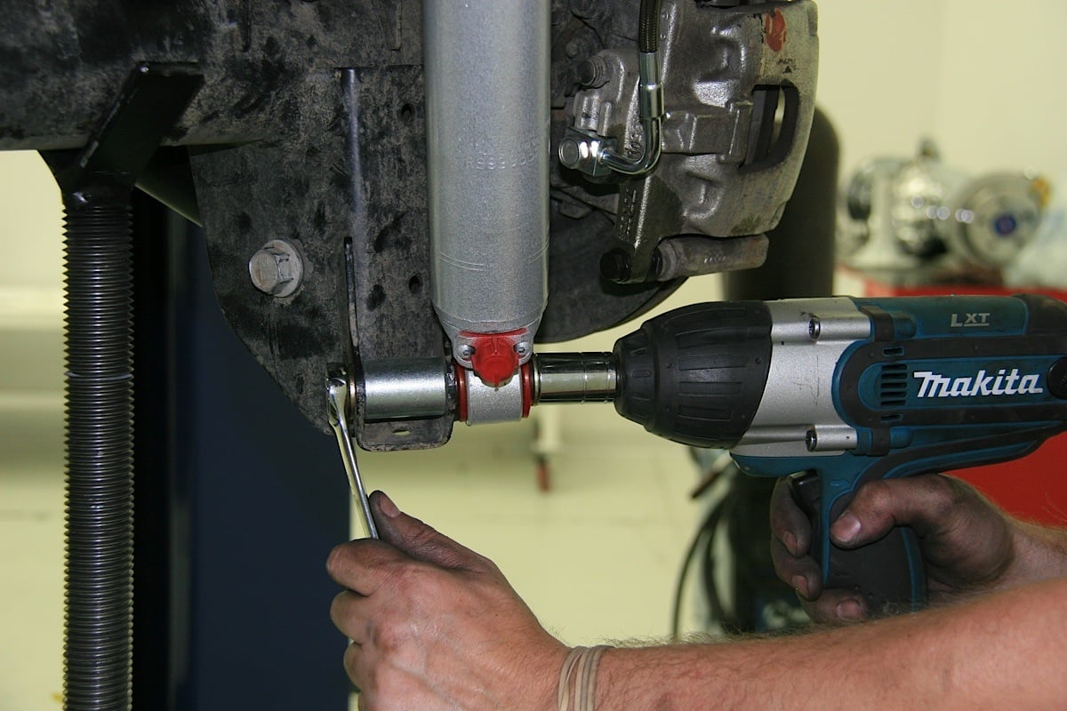
We installed the rear shock relocator brackets on the rear axle, then bolted on the bottoms of the replacement Rancho shocks to the bracket. The tops of the new rear Rancho shocks were connected to their mounts on the Jeep's underside next.
The last thing we did on the back of the Jeep, at this point anyway, was to install the Currie rear shock relocator bracket kit and the rear Rancho RS 9000XL shocks on the outside of the bracket. All the hardware on the rear suspension was tightened to factory specifications. We will re-install the new rear track bar and finish installation of the rear Antirock Sway Bar Kits last, but for now, we’ll move on to the front end.
Up Front
The first thing that needs to happen on the front end of the Jeep is to use a jack to support the front axle while all the stock steering gear such as the tie rod, drag link, and pitman arm is removed. Then, we installed the Currie kit supplied drop pitman arm and torqued it down to factory specs.
 [20]
[20]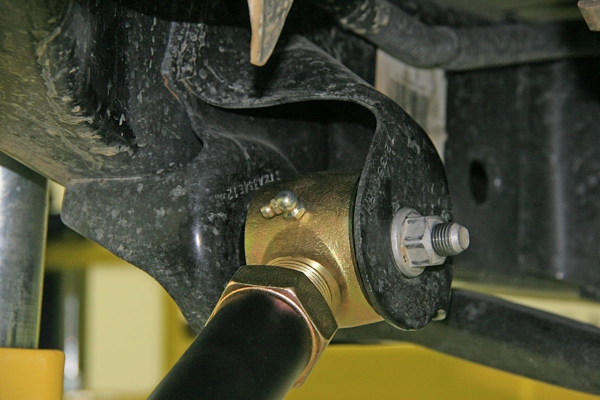 [21]
[21]
After removing the stock anti-sway bars, front track bar, front shocks and springs, and steering gear, we began installing the new Currie front control arms one by one. On the lower arms (right), the adjustable Johnny Joints go to the frame.
We also removed the stock anti-sway bar links, the front track bar, and the front shocks. The front axle was lowered slowly so the front coil springs could be removed too, but use caution, as the springs may fall.
Then we removed the front control arms and replaced them with the new Currie front control arms featuring zerk-fittted greaseable Johny Joints. Replace one arm at a time. In every case but one, the factory bolts are used to re-install them. You must cut the passenger side upper control arm bolt at the frame. New 1⁄2-inch replacement bolts are supplied, and it may be necessary to drill out the upper control arm mount with a 1/2 inch drill.
The lower arms measure 22-5/8 inches and the upper arms are 18-3/4 inches, center to center. Make sure the grease fittings are on the same side when adjusting the arms. On the top arms the grease fittings should point down, whereas on the lower arms the grease fittings should point up. On the lower arms the adjustable end (Johhny Joint) goes on the frame. Do not completely tighten these bolts at this time.
 [22]
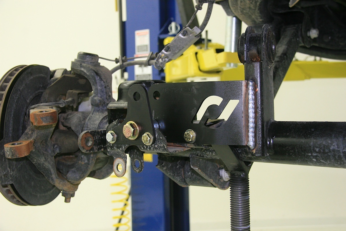
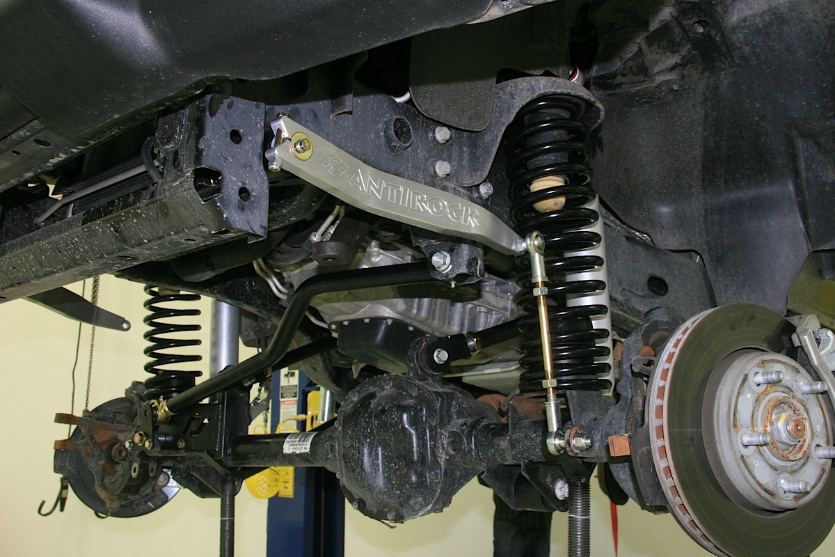
[22]The Currie replacement front track bar mount bracket is bolted and welded into place.
The stock front track bar had already been removed so we could tackle the installation of the Currie front track bar relocator kit. This, as with the rear track bar relocator bracket, will require some welding. Again, as with the rear, when the front track bar relocator brackets are in place, you’ll note where to remove some paint from the parts to which the bracket will be welded.
The large Currie bracket plate was placed inside the factory bracket and the 3/8-24 x 1-inch bolt used in the lower right hole. The small Currie bracket plate was placed on the front of the factory bracket using the 3/8-24 x 1-inch bolt in the lower right hole. The small spacer was inserted between the rear bracket and the factory bracket, with the 3/8-24 x 3-inch bolt on the lower left hole and bolt going through. Then the large spacer was used just like the small one in the previous step, but in the center location, and run through with the 9/16-18 x 3.25-inch bolt. We then tightened the lower right bolt on the back bracket.
 [23]
[23]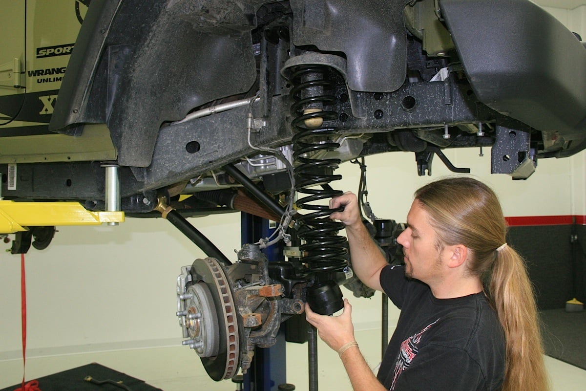 [24]
[24]
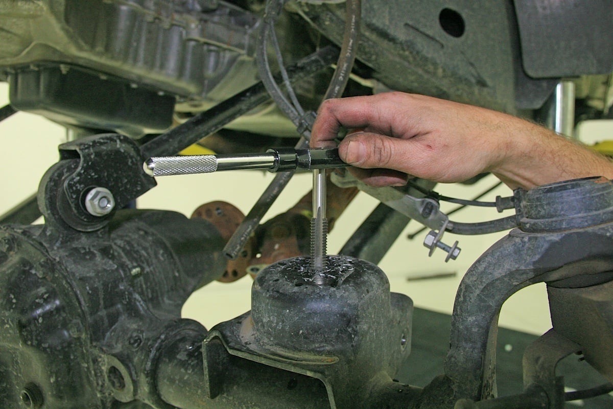
New holes must be drilled and tapped to accept the new Currie front bump stop mounting hardware. The front springs were placed inside their top mount first, then the bump stops slid inside the springs from the bottom to make mounting easier.
At this point the new Currie adjustable track bar was installed and tightened up, then all the other hardware on the track bar bracket was tightened. We used a C-clamp to make sure the metal parts to be welded made full contact, and then laid a nice clean bead down to join the rear piece of the front track bar relocator bracket to the factory upper control arm.
The Currie bump stop kit and the new springs must be installed before we can put the shocks on the front. The bump stop kit requires some drilling and tapping. We first used the front bump stops to help located the center of the lower front spring perch and while holding it, used a punch to create a pilot to begin drilling.
 [25]
[25]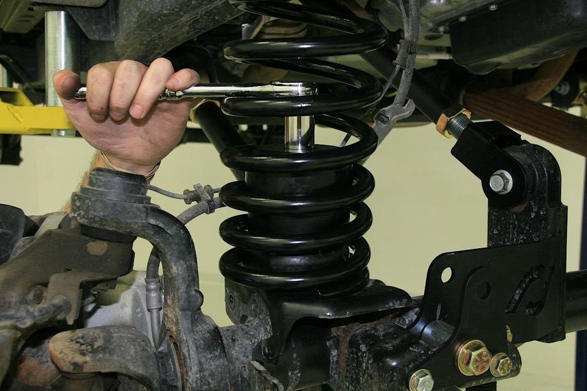 [26]
[26]
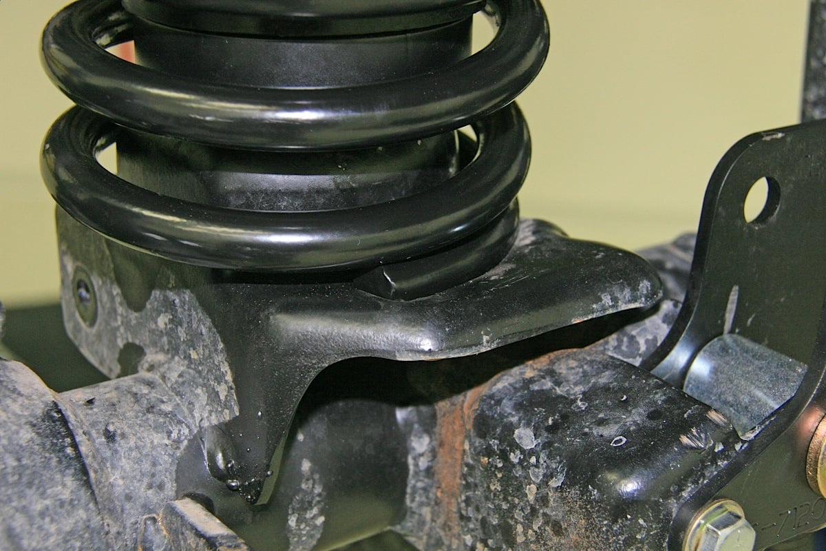
With the bump stops inside, the spring bottoms can now be slid on to their axles perches where a notch will catch and retain the bottom of the coil. We then bolted down the front bump stops from inside the the coil spring using the kit supplied hardware.
A hole was drilled with a 7/16-inch bit in each spring perch and then threaded with a 1/2-13 tap. To install the bump stop, it’s easier to place the bump stop and spacer inside the new spring, install the spring, and then pass the bolt and washers through to install (with some Red Loc-Tite) the Currie front bump stop.
The goalpost-shaped upper shock mounts of the Currie front shock relocator kit can now be installed. These are mounted in the upper shock perches with their flanges turned upside down and the threaded bolt going upward using the kit supplied 5/8-inch nut and 1/2×1-3/8-inch thick flat washer. Then the new Currie kit supplied stainless steel braided replacement front brake lines were installed, and the ABS sensor re-attached to the brake line with the provided zip ties.
The top of the new Rancho RS9000XL shocks (available through Currie Enterprises [27]) we chose for this application were then installed using the 1/2-20×2-3/4-inch bolts, 1/2-20 stover nuts, and 1/2-inch washers. The bottoms of the new Rancho shocks were mounted to the stock perches using the factory hardware.
Beefy Steering
Once the new bump stops, springs, and shocks were all mounted up and hardware completely tightened, we could turn to finishing the installation of the Currectlync steering system [8]. “The optional steering replacement kit is very heavy duty to handle larger tires in tough terrain. The link bar threads are 1-1/4-inch and the bars are 1-5/8-inch 4130 cromoloy heated treated steel,” said Brain Shephard.
 [28]
[28]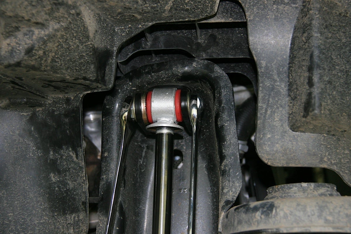 [29]
[29]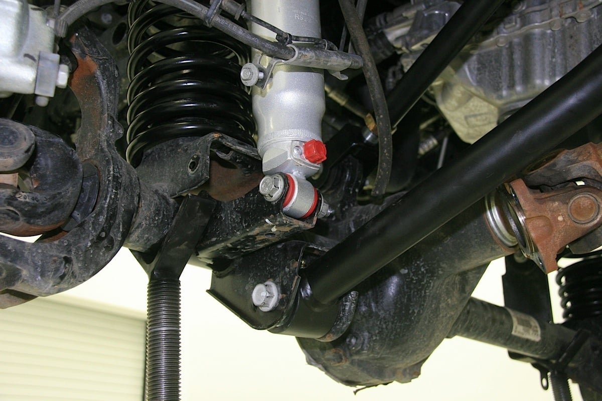 [30]
[30]
The goal post-shaped upper shock mounts were installed using kit supplied hardware, then the new Rancho shocks were mounted in them. Once the top ends of the shocks were mounted, the bottoms could be fastened in their stock lower mounts.
The Johnny Joints were assembled to the massive new tie rod and drag link; and we measured the stock drag link and tie rod so we could adjust and match the lengths of the corresponding replacement Currie parts as a starting point. Reassembly of the steering system was accomplished using the factory hardware.
Antirock Bars
As with the rear, we chose to install the front Currie Antirock Sway Bar links to the front end during the installation of the Currie RockJock Off Road Suspension [4] on Sgt. Rocker because the axles were bare of any extraneous parts and it just seemed easier to do so then. The front sway bars are a simpler installation than the rear so we began there.
 [31]
[31]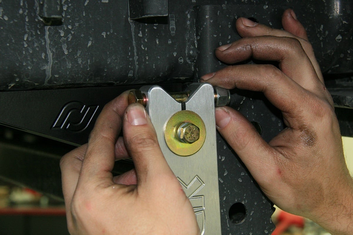 [32]
[32]
 [33]
[33]The front Currie Antirock Sway Bar mounts were fastened in position (top left), the torsion bar was slid through them and the arms installed (top right). The links were attached to arms and axles (bottom).
The driver side Antirock mount was installed in the factory anti-sway bar mount location using factory hardware. We slid the Antirock bar through the installed mount. The second mount was installed on the passenger side and then the bar slid through it too.
We then installed the Antirock arms on each end of the bar that protruded from the sides of the mounts, making sure the arms were “clocked” the same. Once the arms were moved through their full swing of movement to make sure there was no interference, they were attached to the previously installed links.
Back Bar
To begin installation of the rear Currie Antirock sway bars, we replaced the rear brake lines first and relocated the top ends of the kit supplied new lines to 5/8-inch holes drilled in locations near the rear shock top mounts. The bottom ends of the kit supplied replacement brake lines were attached to the factory locations on the rear calipers.
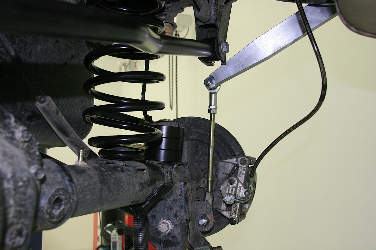
 [34]
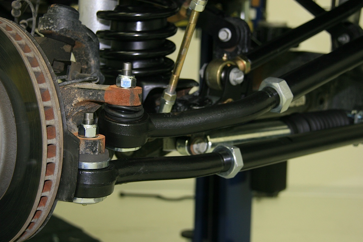
[34]The Currectlynk heavy duty steering system components that replace the stock drag link and tie rod, as well as a Rancho steering stabilizer were installed.
Because the Antirock arms will swing in such close proximity to the frame directly behind the tires, the factory brake hard lines that run along the sides of the frame must be relocated and carefully straightened/bent to run along the top of the frame in that area. We plumbed both sides, and attached the hard lines to the tops of the newly located rear replacement kit brake lines.
The next step is to remove the rear factory bumper support brackets and insert the Antirock bar in between the body and the muffler heat shield. This may be easiest done from the rear of the vehicle. We installed the Antirock mounting brackets on the rear bar, making sure the brackets were angled forward.
The hardware from the factory anti-sway bar was used to go through the bumper support bracket and the Antirock mount bracket into the frame. The holes on the bumper support bracket may have to be elongated to properly align with the frame holes.
 [35]
[35]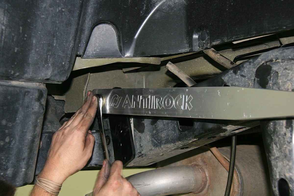 [36]
[36]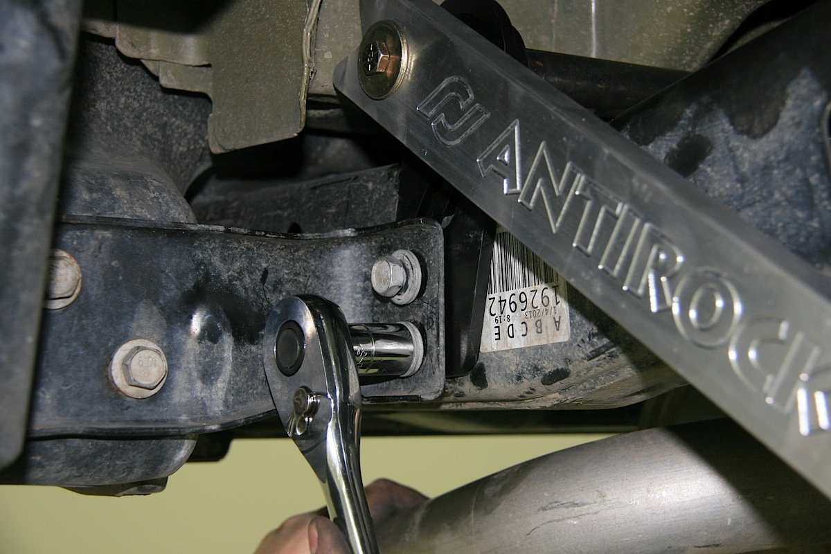 [37]
[37]
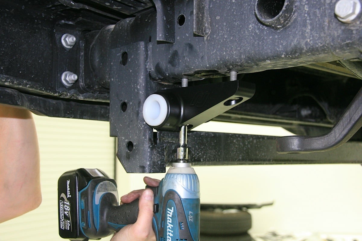
 [38]
[38]We slid the pre-assembled rear Currie Antirock torsion bar and mounts into position atop the frame (top left), the arms were attached to the torsion bar (top center), and then the rear mounts were slid under the rear bumper mounts and attached to the pre-existing bumper mount holes using factory hardware (top right). The links connect the arms to the rear axle (bottom).
Use the kit supplied hardware to fasten the arms to the bars, making sure they are “clocked” to the same position. We have to do a little “clearance” on the Jeep’s body support to prevent the back of the Antirock arm from making contact, you may need to do the same. As with the front arms, before connecting to the end links, rotate the them through their fill range of motion to check for interference.
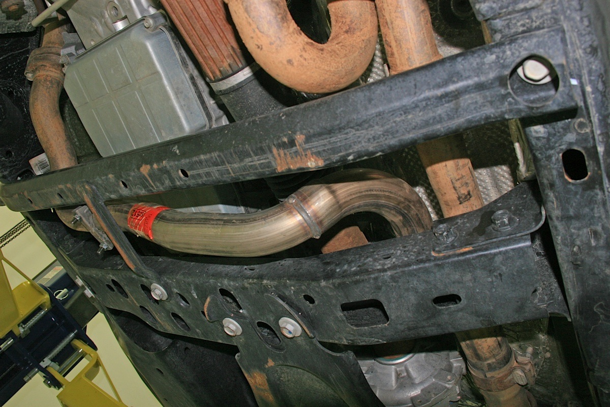 [39]
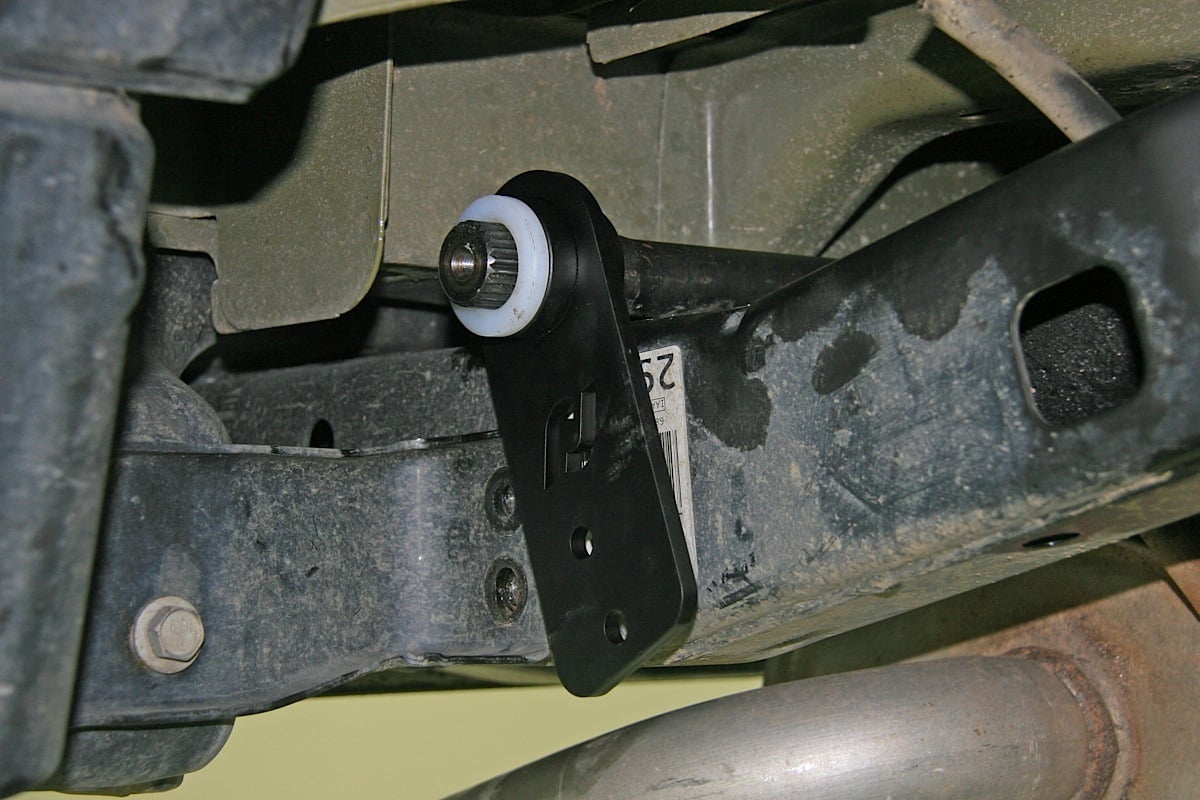
[39]A Rancho Suspension exhaust loop kit was needed to gain extra room for the additional movement the driveline will have due to expanded suspension travel.
Front and rear Antirock Sway Bars need to be adjusted once they are installed, and this should be done while the Jeep is still in the air so that the axles can droop until they reach the the middle of their suspension travel.
Of course, this is different on every vehicle, but it’s “the rule of thumb” and a good place to start. The Antirock arm should be level when the axle assembly is in the middle of its travel. There are longer sway bar link rods available from Currie Enterprises [3] if needed.
Double Check
At this time we went back over all of the suspension, steering, and sway bar hardware to make sure it was tightened to factory specifications. We also filled the brake fluid reservoir and bled the front and rear brakes. Then we bolted on our new Weld Racing REKON wheels and Mickey Thompson Baja ATZ tires.
We also centered the rearend of the vehicle by adjusting the length of the rear track bar. The steering wheel was also centered by adjusting the drag link. At this time we greased every one of the bushings on the suspension arms and track bars.
This suspension kit required an exhaust re-route loop kit from Rancho Suspension [40] (RS720003) to avoid any interference from the front driveline now that it will have significantly more corresponding downward movement in connection with the front differential’s extended travel.
Rancho Suspension’s front control arm skid plate (RS6210), Dana 30 front glide plate (RS6222), and JK Dana 44 rear glide plate (RS6236) were also installed for protection from boulders and other trail obstacles that might damage the Jeep’s vital components while on the trail.
In addition, a new set of heavy duty Canyon Crawler front and rear drivelines from J.E. Reel [41] were swapped in to Project Sgt. Rocker [2] to replace the stock drivelines during the Currie Enterprises [3] RockJock suspension system installation.
 [42]
[42]Almost the last thing we did was bolt up Sgt. Rocker’s new Weld Racing REKON wheels and Mickey Thompson 35-inch Baja ATZ radial tires.
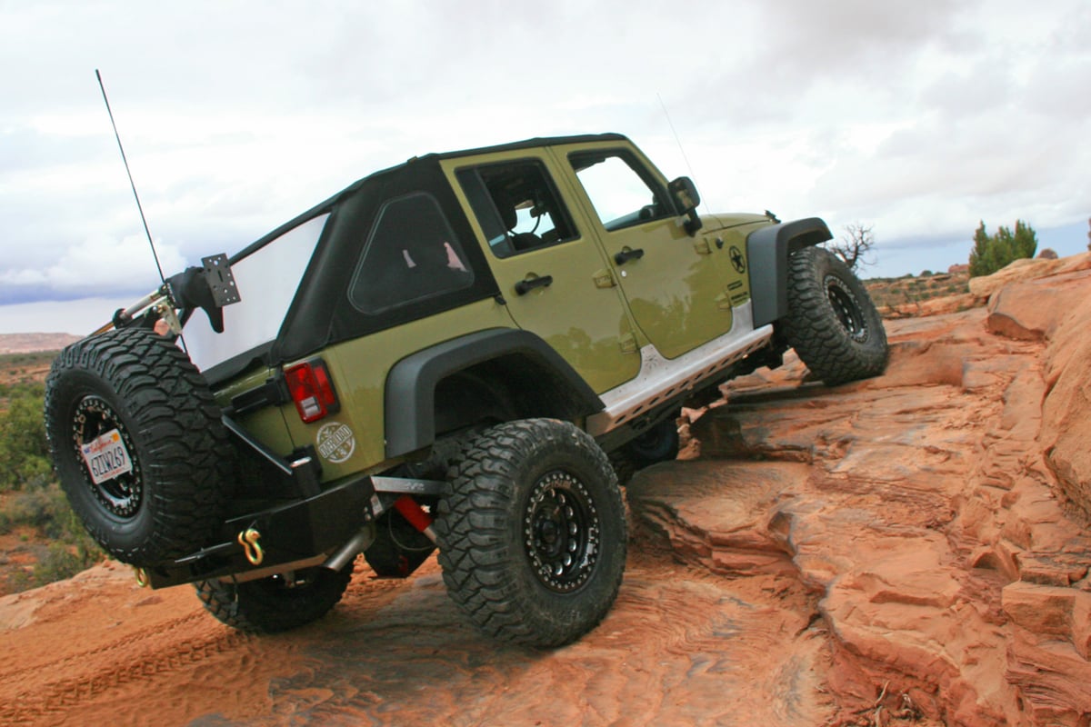
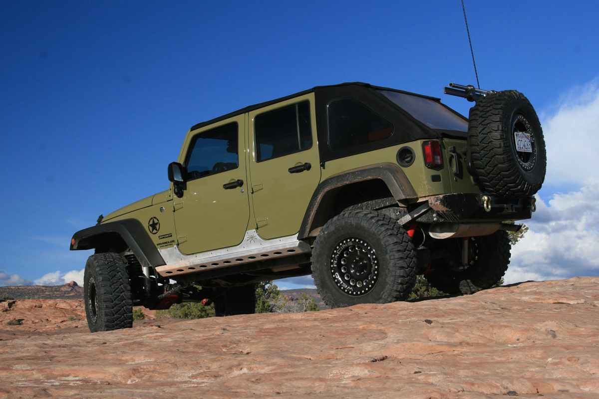
Not long after Sarge received its new longer legs, the Currie Enterprises RockJock [4] suspension system was put to the test over a period of several days during a trip to the Easter Jeep Safari in Moab, Utah. The heavy duty rock crawling on the boulder-filled red sandstone trails of Moab’s outback quickly made it evident that the increased tire height, greater suspension travel, softer spring rates, and more pliable overall system would help the vehicle meet the challenges it faced on the trails.
The Currie Currectlynk heavy duty steering system [8] bolstered Sarge’s ability to man-handle bigger tires and wheels in the rough stuff, and gave us the confidence to drive with bravado. In addition, the beauty of the Antirock Sway Bay systems [6] front and rear are that they act in unison to stabilize the suspension so that when a tire is forced upward on one side of the axle by an obstacle, the torsion bar forces the opposite tire downward.
 [43]
[43]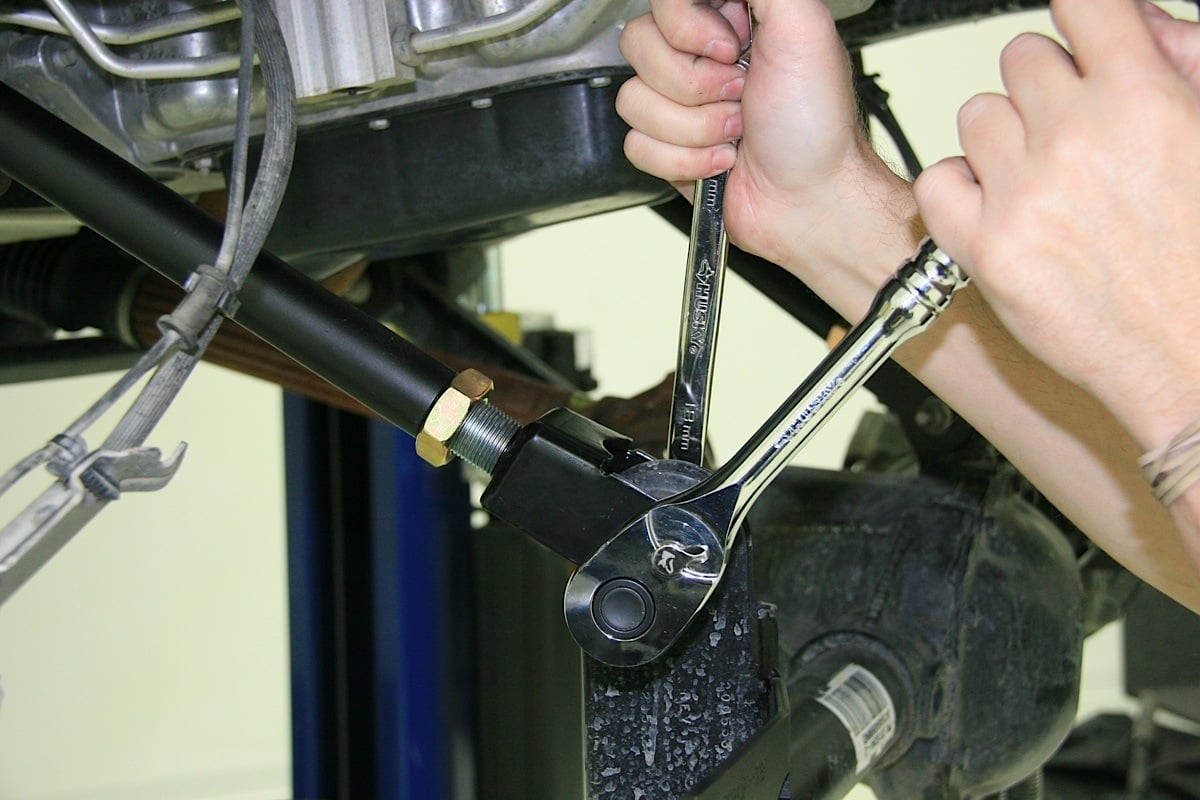 [44]
[44]
A last check to tighten everything completely as well as adjust the tie rod to get the alignment of the front tires as close as possible before taking the Jeep to an alignment shop were among the final checks before buttoning up this installation.
This allows the axles to articulate well, while acting to stabilize the vehicle. As Brian Shephard put it, “When normally the cab of the vehicle would be tilting all over the place and the wife wants to bail out, it pushes the opposite wheel down, helping to maintain traction and forcing all four wheels on the ground, keeping the cab very level.”
In short, we liked what we saw and felt. Our 2013 Jeep Wangler JKU Project Sgt. Rocker [2] stood tall, was saluted by all, and carried its troops through rugged terrain to a safe and successful completion of its mission. What more can you ask of your beloved 4×4?
 [45]
[45]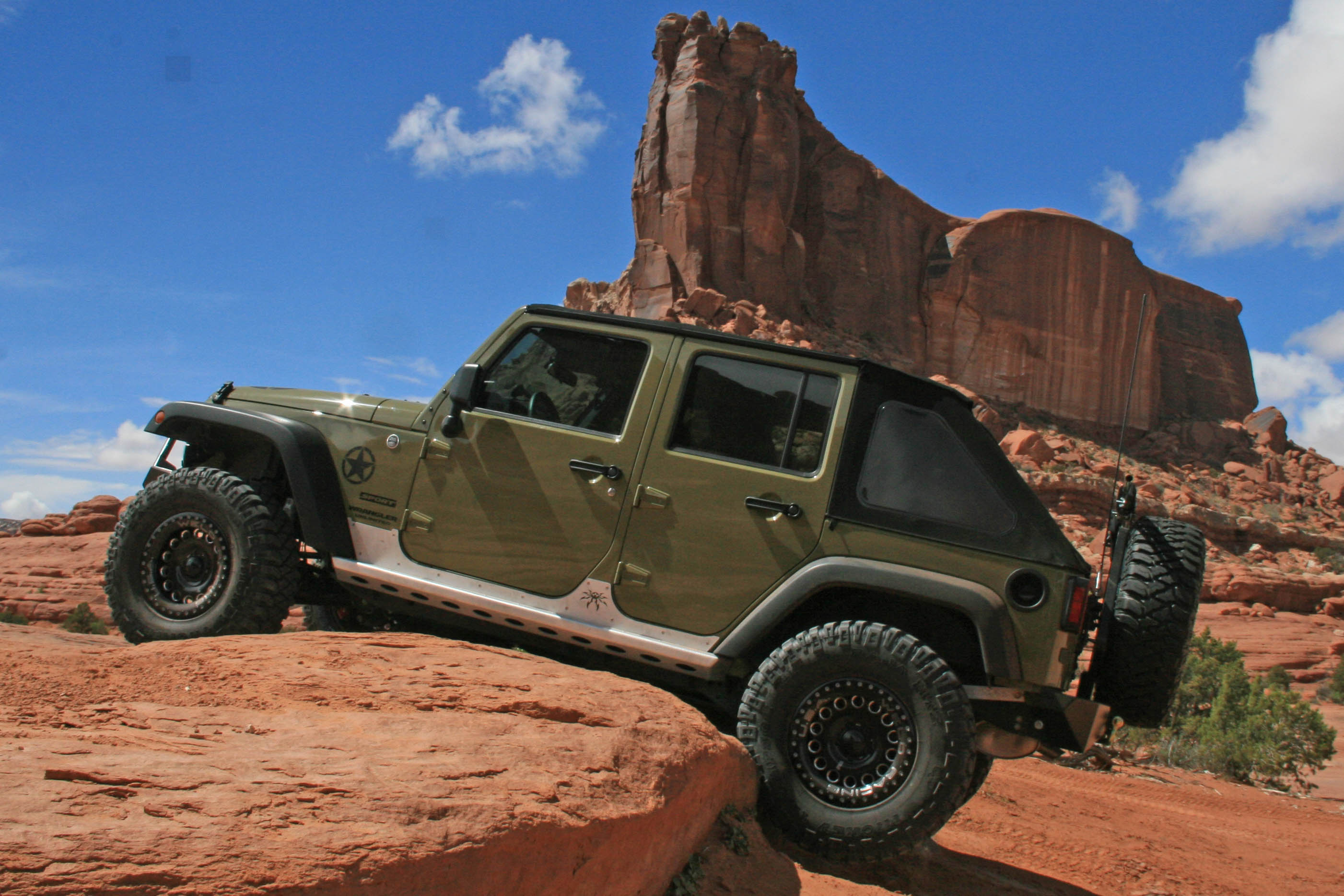 [46]
[46]
 [47]
[47]Our trip to Moab soon after the installation was complete proved to be a good test for the Currie RockJock suspension system. It delivered terrain-hugging articulation, excellent ride characteristics, and smooth jounce and rebound performance.